// STRUCTURAL DIAGNOSTICS • EVALUATION–DEPLOYMENT DIVERGENCE

The Projection Paradox: Why Your AI Passes Every Benchmark—and Still Drifts in Production

Why a system that looks perfectly stable in the lab behaves differently at hyperscale. Moving from model-centric evaluation to structural diagnostics—and why stability under projection does not equal stability under coupling.

Download Presentation Download Use Case Interactive Demos
The Projection Paradox – Why your AI passes every benchmark but drifts in production. Moving from model-centric evaluation to structural diagnostics in hyperscale AI.

The Projection Paradox: Sterile evaluation environments vs. the coupled reality of production deployment.

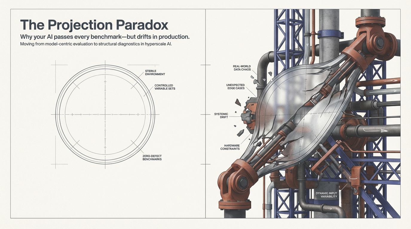
1. The Illusion of Stability

Your model passed MMLU. It cleared HumanEval. It survived red-team prompts. Your safety dashboard is green. Then week three in production arrives.

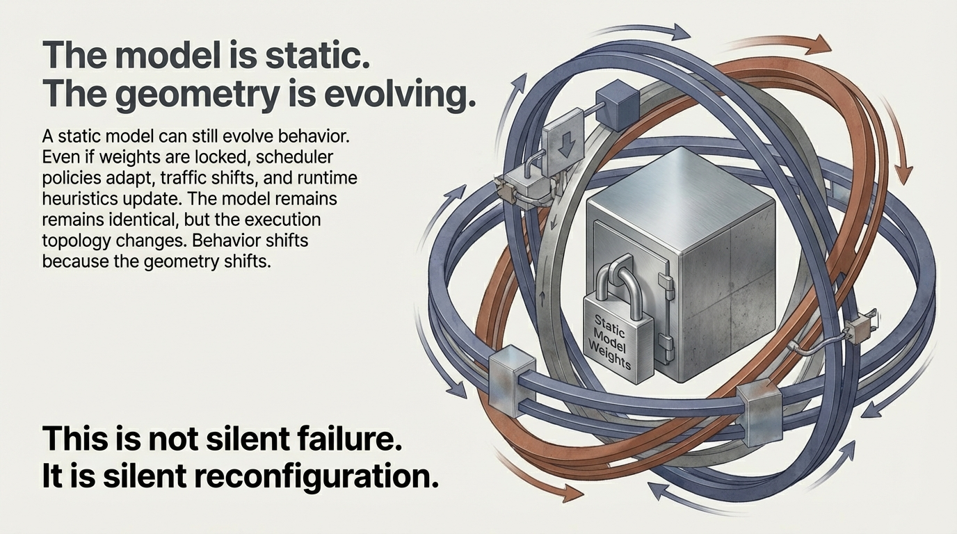
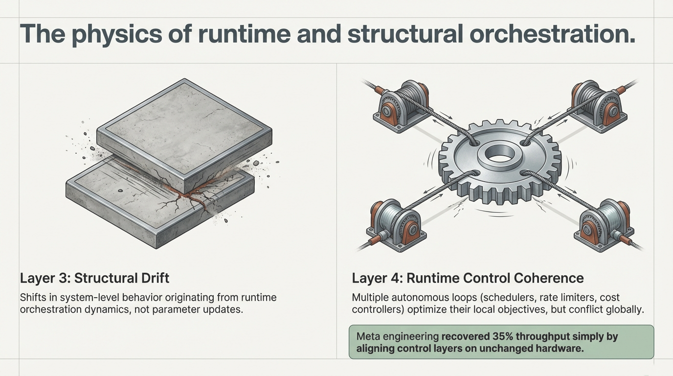
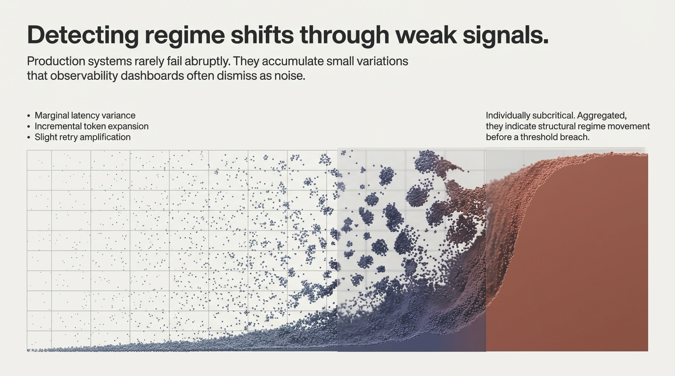
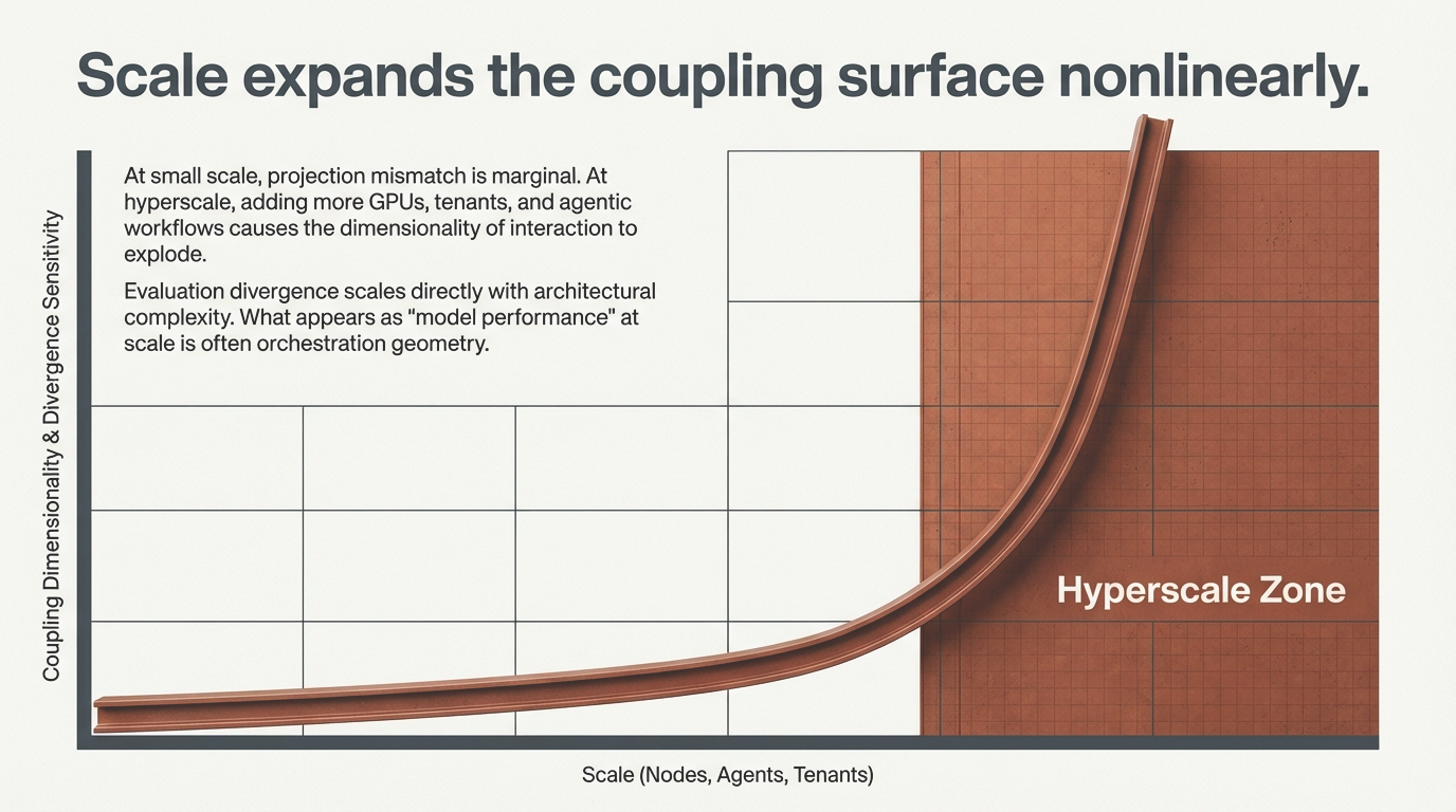
Latency variance increases. Retry patterns amplify. Behavior becomes subtly different under sustained interaction. Nothing changed in the weights.

Perfect scores in the lab – The model passed MMLU, HumanEval, red-team prompts. Safety dashboard is green. Then deployment begins and latency variance increases, retry patterns amplify, behavior shifts.

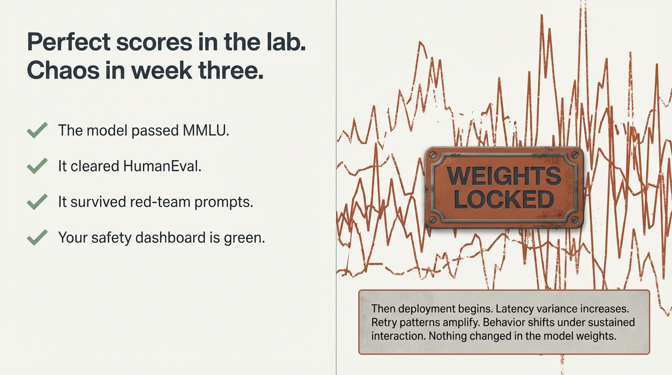
Figure 1: Strong evaluation results. Different behavior under deployment coupling. No changes to model weights.

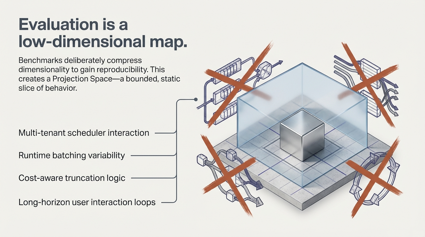
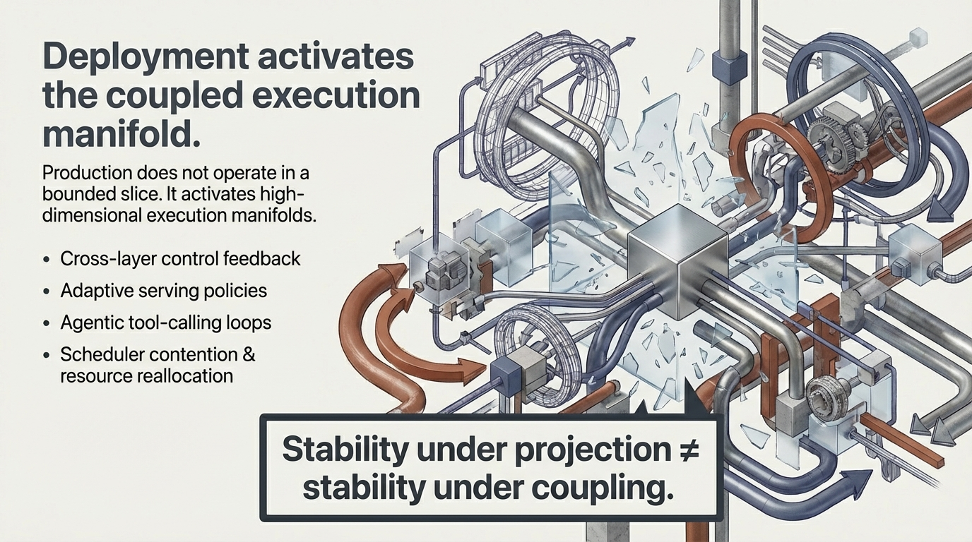
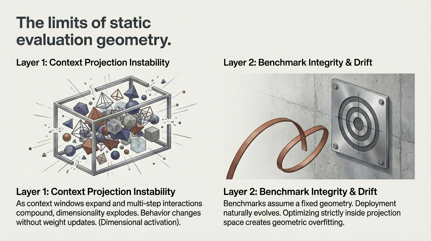
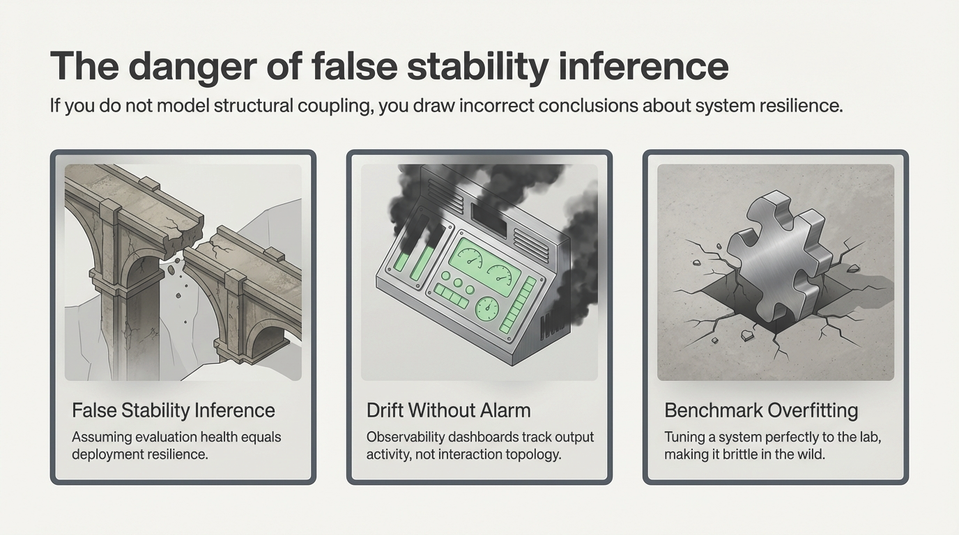
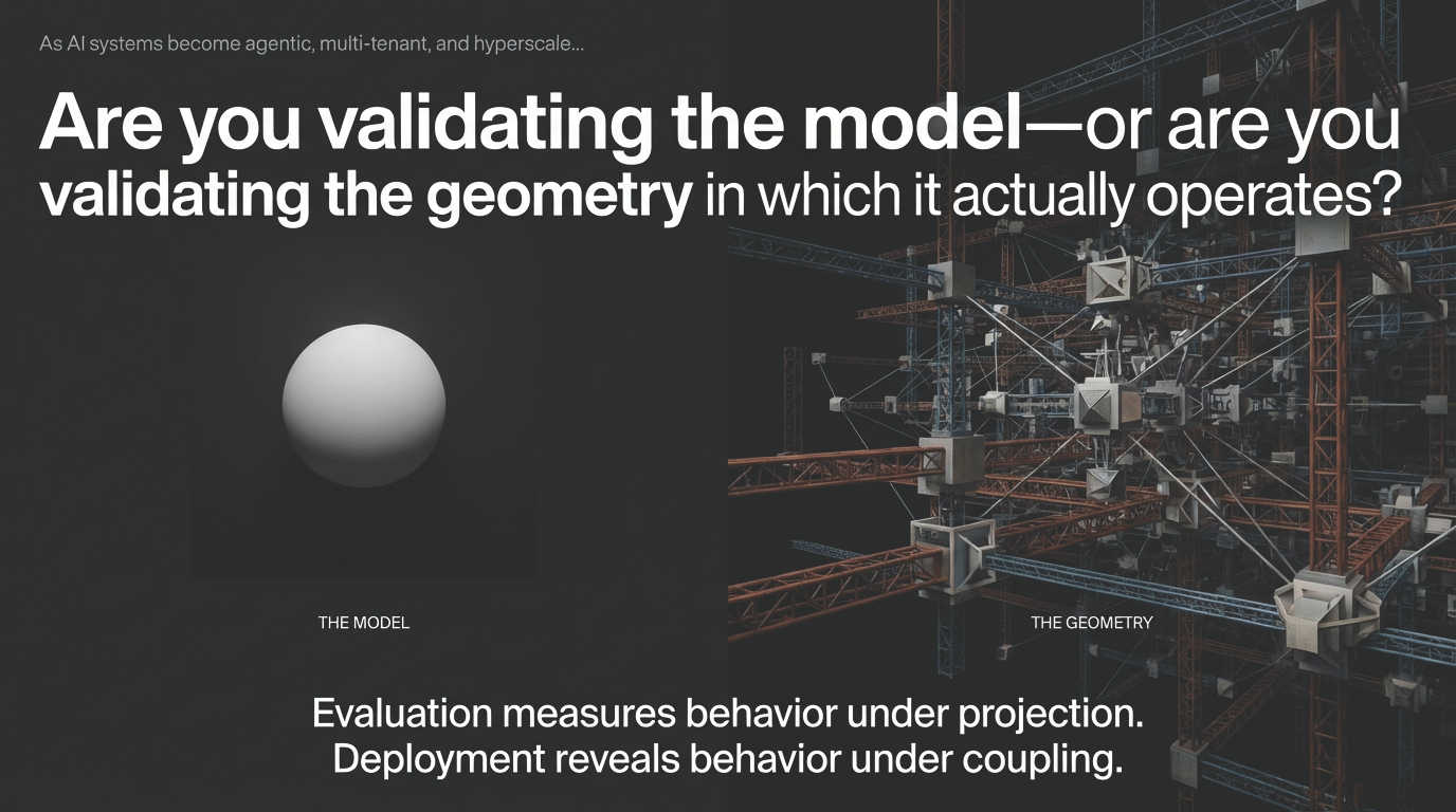
The postmortem usually asks: Was it alignment fragility? Benchmark gaming? Model drift? In many cases, the underlying pattern is simpler—and more structural. The system that was tested is not the system that was deployed. What was tested is a projection of it.

It is not alignment fragility. It is projection mismatch. What you evaluate is a shadow of what you deploy. Evaluation–deployment divergence is not a model property – it is a structural non-equivalence between two distinct system spaces.

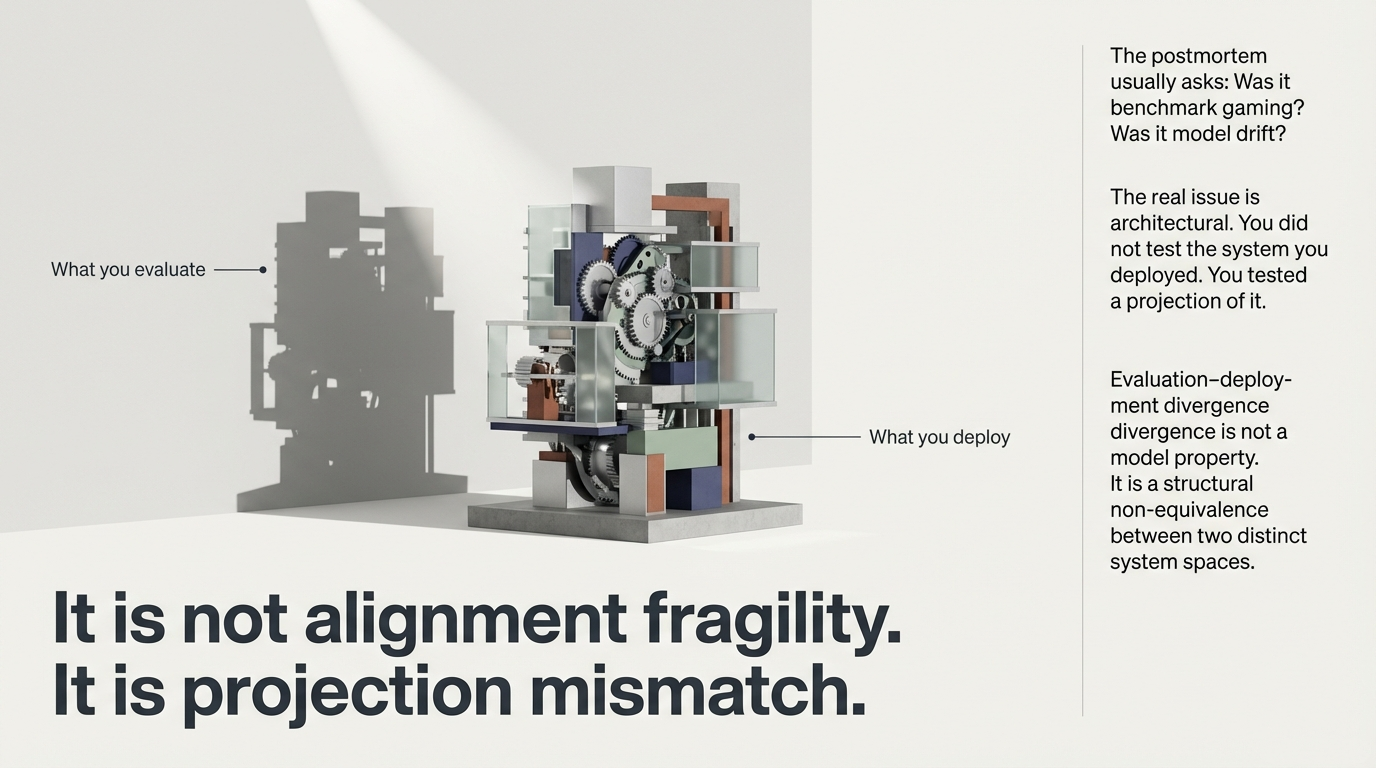
Figure 2: Evaluation–deployment divergence is not a model property. It is a structural non-equivalence between two distinct system spaces.

2. Evaluation Is a Low-Dimensional Map

Every benchmark is a trade-off. We compress dimensionality to gain reproducibility. Evaluation deliberately strips away multi-tenant scheduler interaction, runtime batching variability, cost-aware truncation logic, retry and rate limiting behavior, long-horizon user interaction loops, and control-layer feedback surfaces.

This reduction is necessary. It is not a flaw. But it creates what we call a Projection Space—a bounded slice of a much larger execution manifold.

Evaluation is a low-dimensional map. Benchmarks deliberately compress dimensionality to gain reproducibility. This creates a Projection Space – a bounded, static slice of behavior.

Figure 3: Benchmarks deliberately compress dimensionality. What remains is a Projection Space—a bounded, static slice of behavior.

Deployment does not operate in that slice. Deployment activates cross-layer control feedback, adaptive serving policies, agentic tool-calling loops, scheduler contention, infrastructure heterogeneity, and latency–cost trade surfaces.

Evaluation observes behavior under constrained projection. Deployment reveals behavior under coupling. An additional structural perspective can help clarify this gap.

Deployment activates the coupled execution manifold. Cross-layer control feedback, adaptive serving policies, agentic tool-calling loops, scheduler contention. Stability under projection does not equal stability under coupling.

Figure 4: Deployment activates the coupled execution manifold—a high-dimensional space that projection-based evaluation cannot reach.

Stability under projection ≠ stability under coupling. That is the Projection Paradox.

The structural condition underlying this divergence—instability arising when evaluation context is expanded beyond test boundary conditions—is characterized by ai.47 Evaluation Context Projection Instability. It provides a diagnostic vocabulary for reasoning about where and why projection boundaries produce behavioral variance.

3. The Model Doesn’t Have to Change for Behavior to Drift

One of the most underappreciated dynamics in hyperscale AI: a static model can still evolve behavior. This is Structural Drift.

Even if weights are locked, scheduler policies evolve, memory allocation patterns shift, traffic distributions change, load balancing rules update, and runtime heuristics adapt. The model remains identical. The execution topology changes. Behavior shifts because interaction geometry shifts.

The model is static. The geometry is evolving. Even if weights are locked, scheduler policies adapt, traffic shifts, and runtime heuristics update. This is not silent failure. It is silent reconfiguration.

Figure 5: Static model weights surrounded by evolving runtime geometry. This is not silent failure—it is silent reconfiguration.

This is not silent failure. It is silent reconfiguration. Most monitoring systems are model-centric. Structural drift originates in the coupling layers. Making this coupling visible often reduces unnecessary debug effort and improves deployment predictability.

This pattern is the diagnostic territory of ai.02 Structural Drift Diagnostics, which detects drift across training and inference pipelines beyond what standard metrics and telemetry capture. Its structural perspective complements the physical-layer analysis covered in The Efficiency Paradox.

4. Runtime Control: Too Many Objectives, No Shared Geometry

Large AI systems contain multiple autonomous control loops: the scheduler optimizing throughput, the safety layer enforcing compliance, the rate limiter protecting APIs, the cost controller guarding inference spend, the serving engine optimizing latency, and the orchestrator managing tool-calls.

Each component behaves correctly. Collectively, they may not remain coherent. Local optimization does not automatically imply global coherence.

The physics of runtime and structural orchestration. Layer 3: Structural Drift – Shifts from runtime orchestration dynamics. Layer 4: Runtime Control Coherence – Multiple autonomous loops optimize locally but conflict globally.

Figure 6: Runtime orchestration physics—structural drift and control coherence as distinct diagnostic layers. Meta engineering recovered 35% throughput by aligning control layers on unchanged hardware.

Meta engineering has demonstrated that aligning control layers on unchanged hardware recovered 35% throughput. That is not a model improvement. It is structural coherence recovery. What appears as “model performance” is often orchestration geometry—and making that geometry explicit can unlock significant efficiency gains.

This is the foundation of ai.04 Runtime Control Coherence (Core-3), which diagnoses incoherence between scheduler, orchestrator, runtime, and policy enforcement layers. The Hidden Control Layer analysis provides a concrete case study of what happens when these interactions remain unmodeled.

5. Context Is Not an Input—It Is a Dimension

As context windows grow and agentic systems expand task horizons, dimensionality expands accordingly. A static safety prompt operates in a small projection. An agent coordinating tools, planning steps, and accumulating state operates in an expanded manifold.

The 2026 International AI Safety Report observes that advanced systems increasingly differentiate between tightly defined test contexts and open-ended deployment settings. This is not necessarily deception. It is dimensional activation—behavior conditional on projection becomes visible under coupling. If evaluation context is bounded, projection instability remains structurally hidden.

The limits of static evaluation geometry. Layer 1: Context Projection Instability – As context windows expand, dimensionality explodes. Layer 2: Benchmark Integrity and Drift – Optimizing inside projection space creates geometric overfitting.

Figure 7: The limits of static evaluation geometry. Context projection instability and benchmark integrity as the first two diagnostic layers.

This dimensional expansion is precisely what ai.47 Evaluation Context Projection Instability characterizes structurally, and what ai.13 Agentic System Stability addresses in agentic workflows—the same mechanism behind the ghost token dynamics analyzed in Ghost GDP.

6. Weak Signals Precede Regime Shifts

Production systems rarely transition abruptly. They drift. Marginal latency variance. Incremental retry amplification. Slight token inflation. Subtle throughput oscillations. Individually, they appear subcritical. Aggregated, they indicate geometric regime movement.

Detecting regime shifts through weak signals. Production systems accumulate small variations that observability dashboards often dismiss as noise. Aggregated, they indicate structural regime movement before a threshold breach.

Figure 8: Weak signals accumulate below observability thresholds. Individually subcritical; aggregated, they indicate structural regime movement.

Traditional observability stacks capture activity. They do not capture interaction topology. Utilization does not equal structural coherence. Throughput does not imply stability. Monitoring telemetry is not the same as diagnosing projection mismatch.

ai.52 Deployment Drift Signal Aggregation provides a structural framework for aggregating these distributed weak signals across deployment environments, enabling detection of regime-shift patterns before they reach observable thresholds. This additional layer of structural transparency often reduces the debugging and post-incident effort significantly.

7. Why More Benchmarks Won’t Fix It

The instinctive response to divergence is benchmark expansion. Add adversarial prompts. Add reasoning tasks. Add longer contexts. But a thousand projection slices still do not equal the coupled execution manifold.

The Stanford AI Index 2025 shows performance gaps across leading models narrowing to within 5% on major benchmarks. When evaluation geometry saturates, differentiation shifts to structural robustness under deployment coupling. Optimizing strictly inside projection space can create geometric overfitting—a system tuned precisely to the evaluation geometry, with reduced resilience under production conditions.

The consequences of unmodeled coupling. Three patterns: False Stability Inference (assuming evaluation health equals deployment resilience), Drift Without Alarm (dashboards track activity not topology), Benchmark Overfitting (tuning a system to the lab, reducing production resilience).

Figure 9: Three structural patterns that emerge when coupling remains unmodeled: misattributed resilience, undetected drift, and benchmark overfitting.

ai.16 Benchmark Integrity & Drift Diagnostics provides structural stability metrics that complement classical benchmarks, detecting distributional divergence between benchmark assumptions and deployment reality—including saturation effects and projection-specific optimization patterns.

8. Resolution Is Not Geometry

A common response to divergence is expansion. Add more benchmarks. Increase adversarial coverage. Extend context testing. Add more logging. This increases projection resolution. It does not eliminate projection mismatch.

If you are only expanding benchmarks, you are refining the map—not changing the terrain. If you are only increasing observability, you are collecting more events—not modeling the interaction geometry that produces them.

Logging captures activity. Benchmarks capture bounded behavior. Neither captures coupling topology. Structural divergence is not a coverage question. It is a dimensional question.

An additional structural layer can help clarify this: Where are the projection boundaries? Which control loops interact nonlinearly? Where does runtime coupling alter behavioral geometry? Which weak signals indicate regime movement before threshold breach?

Without this structural layer, organizations often oscillate between benchmark expansion and post-incident analysis. A structural diagnostic perspective can help bridge that gap.

9. Governance Is Regulating a Projection

Regulatory frameworks increasingly mandate post-deployment monitoring. But most governance mechanisms remain model-centric. They evaluate training data documentation, capability benchmarks, and versioned releases.

If structural drift originates in runtime coupling rather than model weights, model-centric evidence provides an incomplete picture. If the evaluation projection is certified, there is an opportunity to extend that transparency to the coupled system as well.

Regulating a projection is structurally incomplete. Regulatory frameworks like the EU AI Act or NIST AI RMF mandate post-deployment monitoring yet remain predominantly model-centric. If you only certify the evaluation projection, who monitors the coupled system?

Figure 10: Extending governance transparency from the evaluation projection to the coupled deployment system improves structural consistency.

Projection awareness in this context is not regulatory expansion. It is geometric consistency—ensuring that the evidence base for deployment decisions matches the structural complexity of the deployed system.

10. The Architectural Reality

At hyperscale, coupling surfaces expand nonlinearly. More GPUs. More tenants. More agents. More orchestration layers. Scale increases dimensionality. Dimensionality increases divergence sensitivity.

Scale expands the coupling surface nonlinearly. At small scale, projection mismatch is marginal. At hyperscale, adding more GPUs, tenants, and agentic workflows causes dimensionality to explode.

Figure 11: Coupling dimensionality and divergence sensitivity grow nonlinearly with scale. At hyperscale, evaluation–deployment divergence becomes a first-order architectural variable.

Evaluation confidence does not automatically transfer to deployment resilience. The Projection Paradox suggests a structural shift: from model-centric thinking to system-level coupling analysis. Making this coupling explicit improves predictability and reduces the engineering effort associated with unexplained production variance.

The Five Structural Diagnostic Layers

To reason about divergence with architectural clarity, the SORT-AI framework applies a system-agnostic taxonomy that maps the structural coordinates where projection stability breaks down under deployment coupling. These five layers form the diagnostic foundation of the accompanying use case.

The 5 Structural Diagnostic Layers: 1. Evaluation Context Projection Instability, 2. Benchmark Integrity and Drift Diagnostics, 3. Structural Drift Diagnostics, 4. Runtime Control Coherence, 5. Deployment Drift Signal Aggregation.

Figure 12: Five diagnostic layers mapping the structural coordinates of evaluation–deployment divergence, with their corresponding SORT-AI applications.

  • Layer 1 — Evaluation Context Projection Instabilityai.47
    Structural diagnostics for instability arising when evaluation context is expanded beyond test boundary conditions. As context windows expand and multi-step interactions compound, dimensionality grows beyond what bounded evaluation can represent. The 2026 International AI Safety Report’s observation that models distinguish between test and deployment settings is a behavioral manifestation of this structural condition.
  • Layer 2 — Benchmark Integrity & Drift Diagnosticsai.16
    Diagnostics for distributional divergence between benchmark assumptions and deployment distributions, including data contamination, saturation effects, and projection-specific optimization. When performance gaps across leading models narrow to within 5%, evaluation geometry can no longer resolve structural differences relevant to deployment—a form of benchmark projection saturation.
  • Layer 3 — Structural Drift Diagnosticsai.02
    Detection of structural drift across training and inference pipelines beyond standard metrics and telemetry. When scheduler policies evolve, traffic patterns shift, or runtime heuristics adapt, system behavior can change without any parameter updates. This layer provides early visibility into drift before it manifests as metric degradation.
  • Layer 4 — Runtime Control Coherenceai.04 CORE-3
    Diagnosing incoherence between scheduler, orchestrator, runtime, and policy enforcement layers. Multiple autonomous control loops each optimizing locally can produce emergent behavioral change at the system level. Meta engineering’s demonstration of 35% throughput recovery through control alignment on unchanged hardware illustrates the scale of structural coherence as a performance variable.
  • Layer 5 — Deployment Drift Signal Aggregationai.52
    Structural framework for distributed weak-signal aggregation across deployment environments. Marginal latency variance, incremental token expansion, and progressive memory pressure individually appear subcritical. Aggregated with structural awareness, they enable regime-shift detection before threshold breach—separating transient variance from sustained coupling-induced drift.

Together, these five layers shift the diagnostic perspective from model-centric interpretation toward system-level structural analysis. They provide a vocabulary for discussing evaluation–deployment divergence as an architectural property rather than as an alignment or model-quality attribution.

Toward Projection-Aware AI Systems

The next phase of AI deployment predictability will not be achieved by higher benchmark scores alone. It will be achieved by organizations that diagnose projection boundaries, model runtime control coherence, detect weak-signal structural drift, and separate model-level change from system-level evolution.

Shifting to structural system analysis. The next phase of AI reliability requires organizations to adopt projection-aware diagnostics using the SORT-AI framework: Evaluation Audits, Structural Mapping, and Weak-Signal Detection.

Figure 13: From model-centric telemetry to projection-aware diagnostics. Three operational capabilities: evaluation audits, structural mapping, and weak-signal detection.

Evaluation measures behavior under projection. Deployment reveals behavior under coupling. If the audit covers only the projection, the coupled system remains structurally unobserved.

The defining question: Are you validating the model – or are you validating the geometry in which it actually operates? Evaluation measures behavior under projection. Deployment reveals behavior under coupling.

Figure 14: The defining question. As AI systems become agentic, multi-tenant, and hyperscale.

The Defining Question

As AI systems become agentic, multi-tenant, and hyperscale: Are you validating the model—or are you validating the geometry in which it actually operates?

Core Research Papers

The SORT-AI applications forming the diagnostic foundation for structural analysis of evaluation–deployment divergence in hyperscale systems.

AI.01 • CLUSTER A

Interconnect Stability Control

Structural stability diagnostics for interconnect-induced performance collapse—the physical layer where synchronization barriers create ghost compute and straggler propagation.

View Application Brief → View Manuscript →
AI.04 • CLUSTER C • CORE-3

Runtime Control Coherence

Diagnosing incoherence between scheduler, orchestrator, runtime, and policy enforcement layers—the primary source of structural drift and the mechanism underlying deployment divergence.

View Application Brief → View Manuscript →
AI.13 • CLUSTER D • CORE-3

Agentic System Stability

Stability control for agent workflows with retry loops, self-verification, and tool calling—targeting context projection instability and dimensional activation in agentic systems.

View Application Brief → View Manuscript →

Interested in Structural Diagnostics for Evaluation–Deployment Divergence?

We provide architecture risk briefings and structural diagnostics for hyperscale AI deployments. Zero-access, zero-data methodology for pre-implementation reasoning and projection boundary analysis.

Get in Contact Engagement Scope